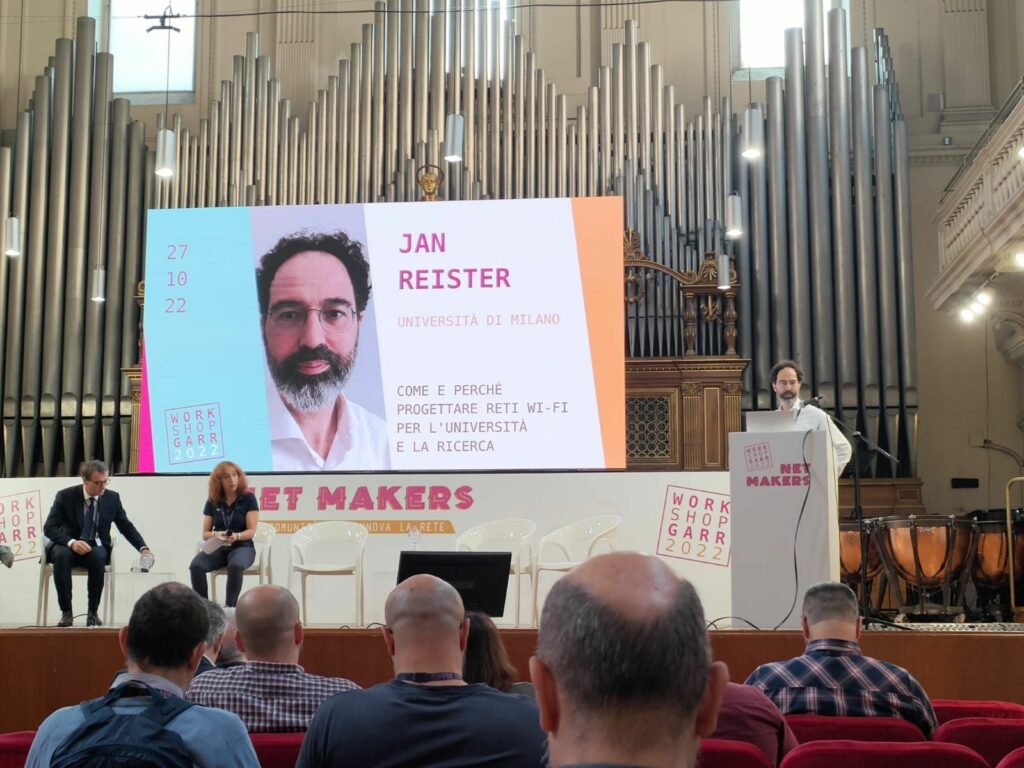
In my talk at GARR Workshop 2022 in Rome, I made the case for professional WLAN design in the Italian university and academic world.
Feedback in the audience has been overwhelming! My thanks to my employer unimi, to GARR and the Italian WLAN community for supporting, contributing ideas and criticism.
Designing wi-fi networks in the academic and research institutions requires specialized knowledge and tools to deal with this sector’s requirements (size, high density, BYOD, student dorms, IoT devices). An investment in knowledge and best practices is needed to design high performance wireless networks. There’s an open, inclusive community of WLAN professionals where problems and solutions are shared, where knowledge and skills grow – worldwide and now also in Italy.
Floor plans in Ekahau Pro designs are strictly 2D. Tri-dimensional features can be added using wall height, AP height and ceiling height in a building artifact, which is basically a stack of floor plans scaled and aligned vertically. In a building, the hole in floor is a powerful tool to render complex features such as balconies, staggered floors, stairwells, courtyards and shafts. Despite all this 3D features, floor plans are strictly horizontal, and cannot represent inclined surfaces, slopes or stadium tiers.
I had to design wi-fi for a small lecture hall recently, and thought I could have some fun stretching Ekahau 3D concepts to the limit and learning something new.
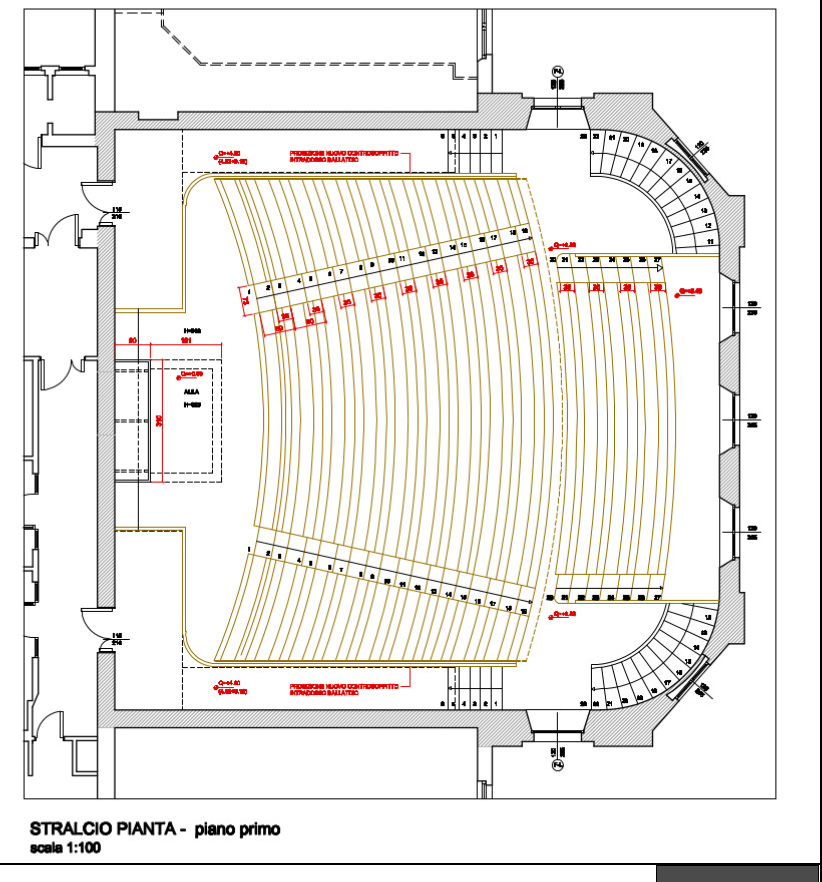
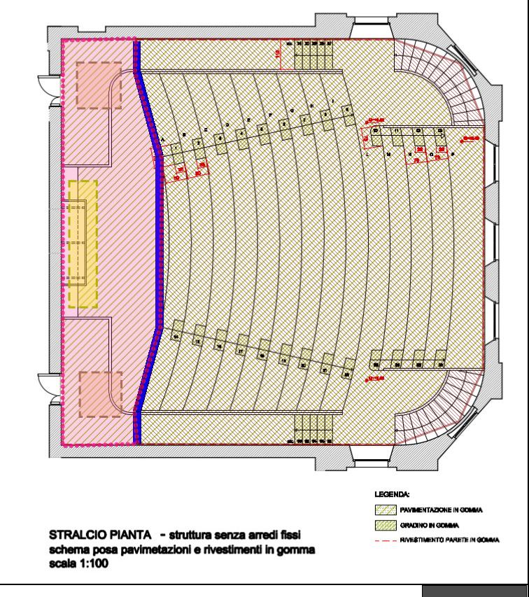
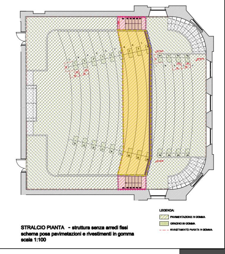
The lecture hall was built in the 1920s with a steep auditorium design that enabled attendees to hear and see the podium without any audio/video technology, even from the farthest seat. It has 13 rows of seats on a stepped floor, each step 40cm high.
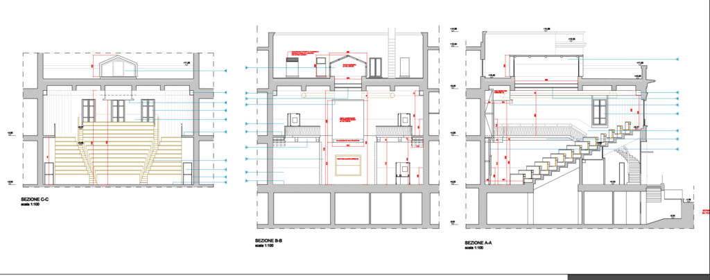
Auditorium, front, back and side section view
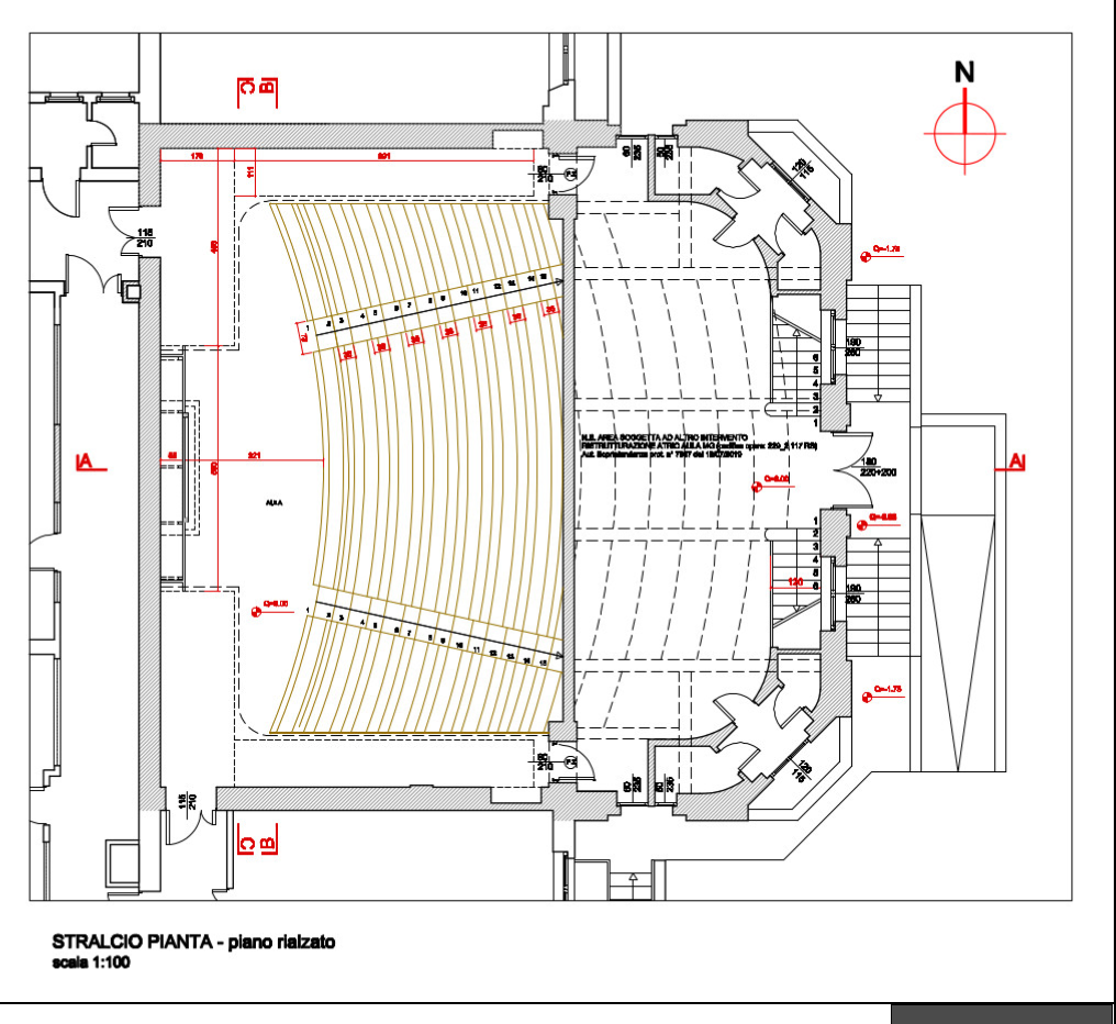
ground floor
first floor view
To simulate the stepped floor I planned a building with 14 identical floor plans (one for each seat row), each floor with 40 cm ceiling height. Using holes in floor I then planned to cut out every floor leaving only the step area, and placing a 40 cm high wall on the step rise.
Lesson learned 1: the minimum ceiling height in Ekahau Pro is 1m. I had to simplify the design by grouping the steps and reducing the building from 14 to 7 floors.
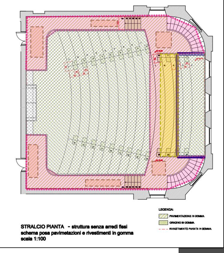
Using the hole in floor tool I cut out the floors, placed a custom 1m high wall to simulate the step rise, and added areas and attenuation areas on the active surfaces on each level.
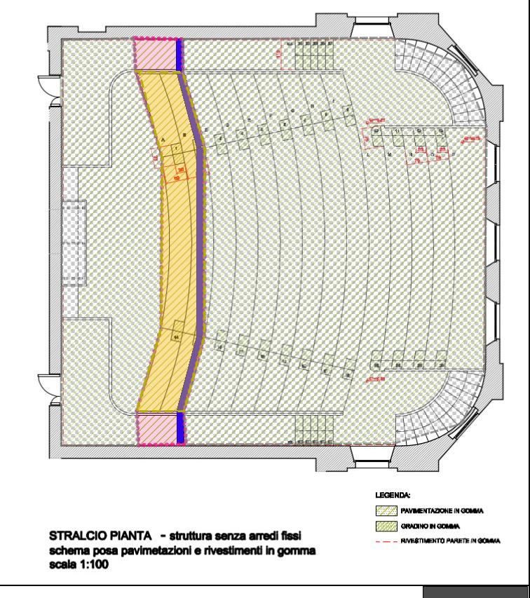
ground floor
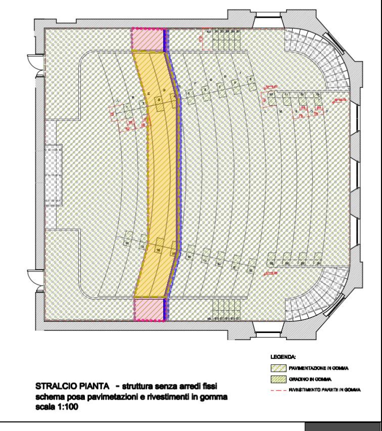
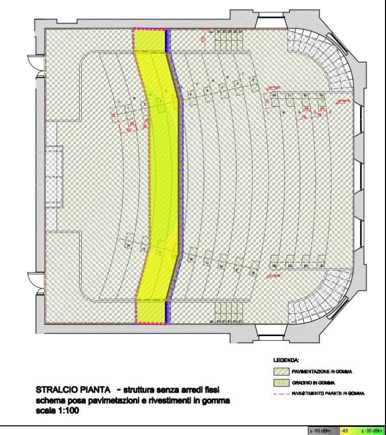
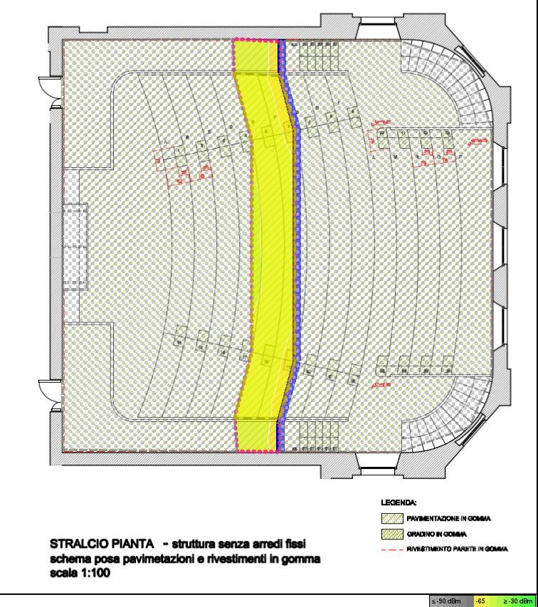
steps 1-2
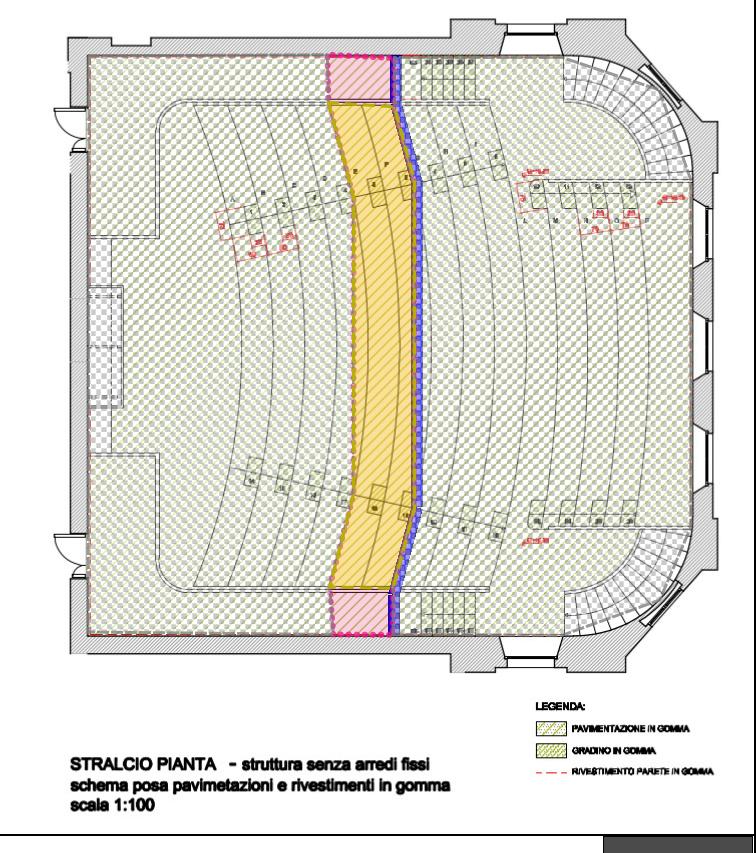
steps 3-4
steps 5-6
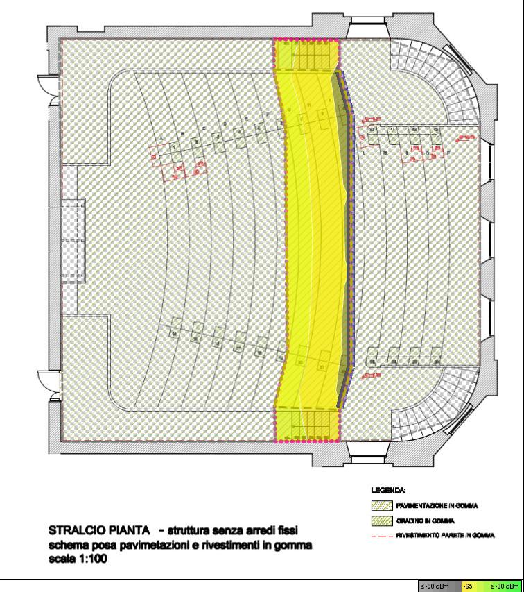
steps 7-8-9
steps 10-11-12
The first 6 stacked floors, each with area, hole in floor, step wall and attenuation areas
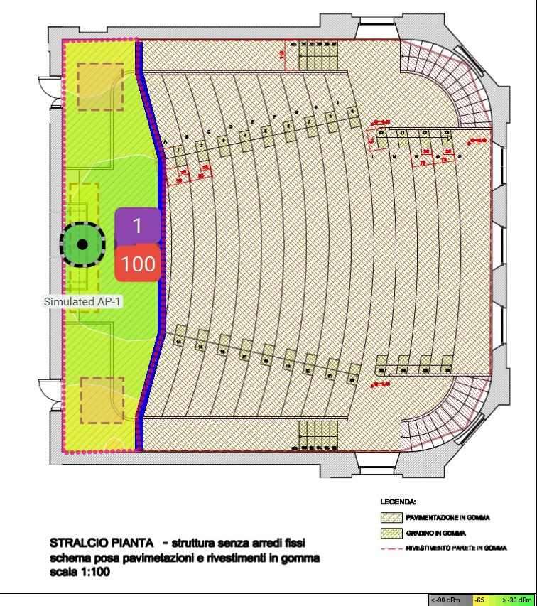
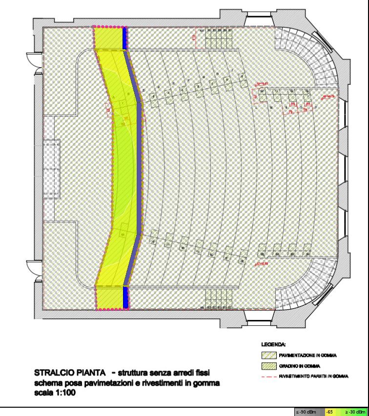
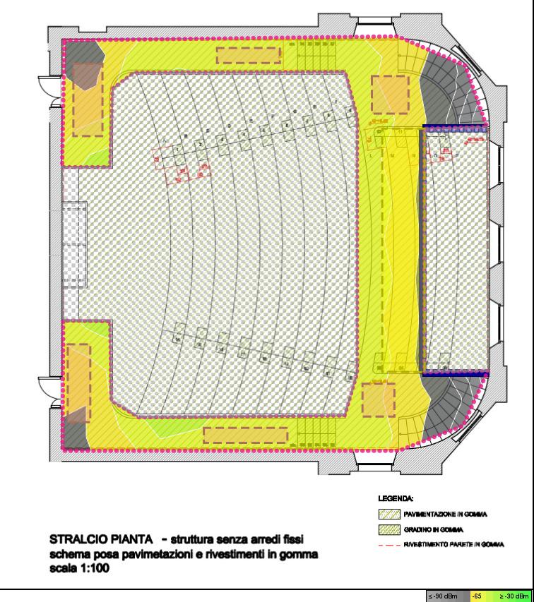
I placed a simulated AP in floor 1 at 4m height and displayed the signal strength at every seat row. Lesson learned 2: even if the ceiling is 1m, the software allows placing an AP higher, regardless of floors above.
At first, the predictive design did not display the RF signal on the all the floors. Lesson learned 3: enable Signal prediction: all floors on the Options button. Please also note that the default visualization height is 1m from the floor, this can be customized with Ctrl+Options.
Playing with the AP position and height allows to explore the different attenuation effects in 3D space. It is an approximation to the real shape of the hall, and of the RF attenuation effects, as good as the Ekahau software goes.
Here is an example of predictive signal strength in 5Ghz, where the attenuation from areas, floors and walls is clearly visible. Besides signal strength, all the usual visualizations are possible; my other favorites are Capacity and Health.
AP at 4m
The signal strength prediction on the stepped seat rows
This technique is fun, but unless there are very specific requirements in designated areas, this kind of auditorium design is an overkill in real life. During surveys, this design would force switching floor plan every few meters. Viewing survey data would also be unpractical.
A much simpler solution was suggested by Ferney Muñoz during the 17a Sesión de Tes@s en Wi-Fi when I gave a small presentation: if the APs are placed on the ceiling at the same height and the auditorium seat rows are stepped, just reduce the AP height accordingly from front to back. In other words, simulate an inclined floor using the APs instead of the floors.
Conclusion:
The floor plan sandwich technique is fun and provides detailed simulation of complex building artifacts…
…but it’s probably terrible for surveys.
The software limits the minimum ceiling height to 1m.
Simulated APs can be placed at any height, regardless of upper floors.
RF signal prediction is done at 1m height from the floor, customizable.
Enable signal prediction to all floors in order to see how an AP impacts the whole 3D model.
Legal note: Ekahau and Ekahau Pro are registered trademarks of Ekahau OY.
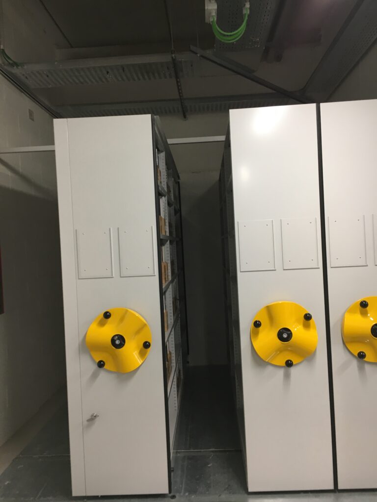
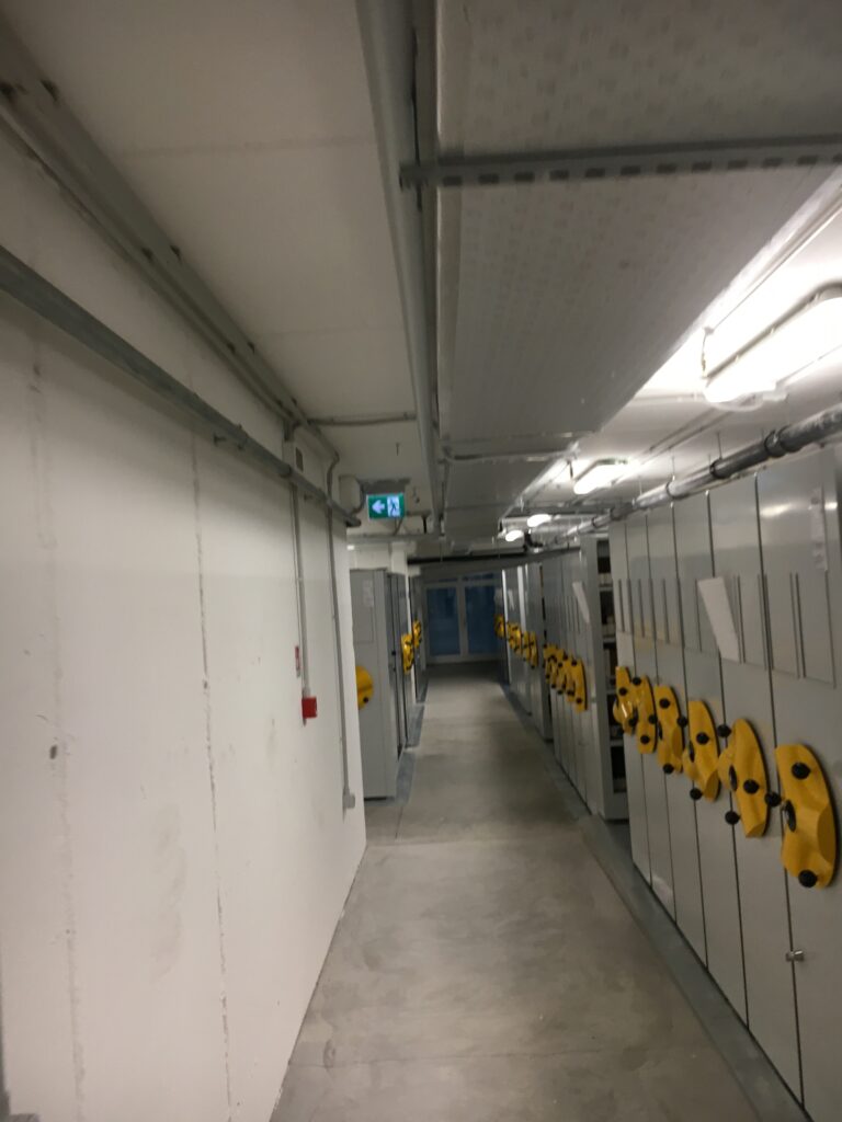
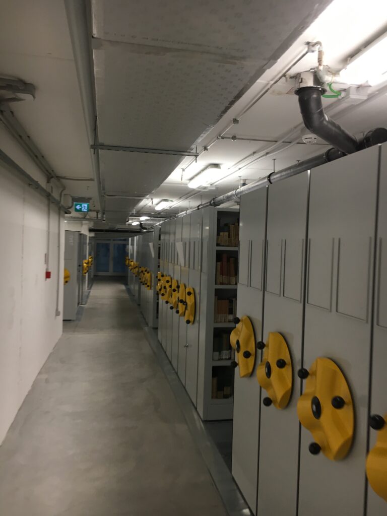
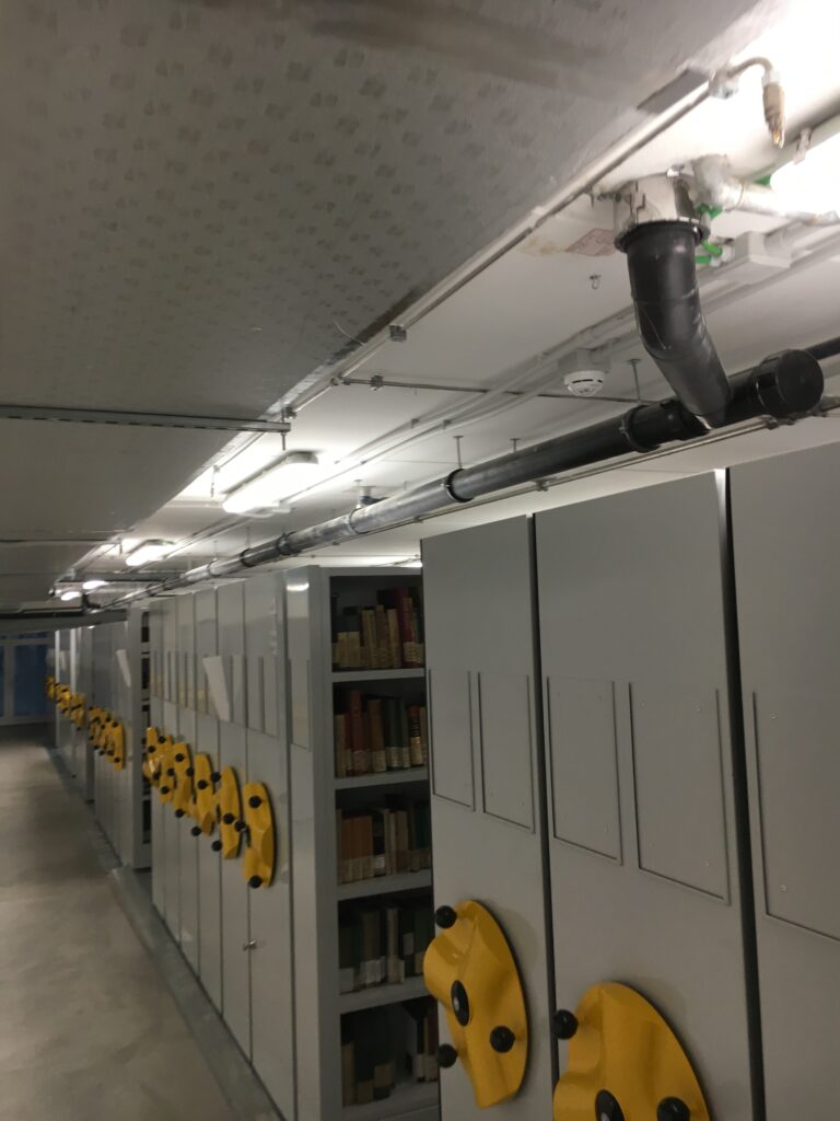
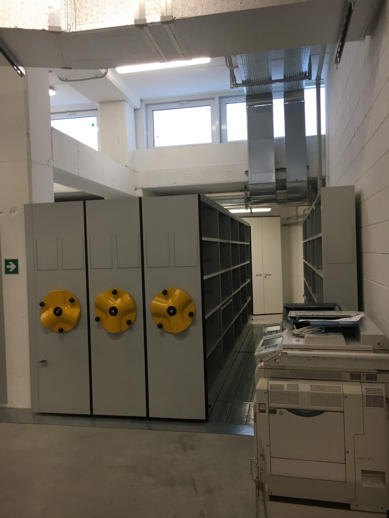
I am doing a project for a library warehouse with compact sliding shelves. It’s a large area in the basement with rows of metal bookshelves.
insert librarian here
caution!
librarian inside
Every shelf is fitted on rails and has a crank that allows sliding an entire row left and right. Once the chosen shelf has been opened wide, a librarian can access the books inside and start working.
It’s basically a warehouse with moving aisles.
During the initial engagement phonecall I asked what the needs for wi-fi were, what type and how many devices had to connect, physical access procedures, security issues. I like to study the floorplans beforehand and prepare an Ekahau project with just the correct scale set, and nothing else.
A sector of the library warehouse.
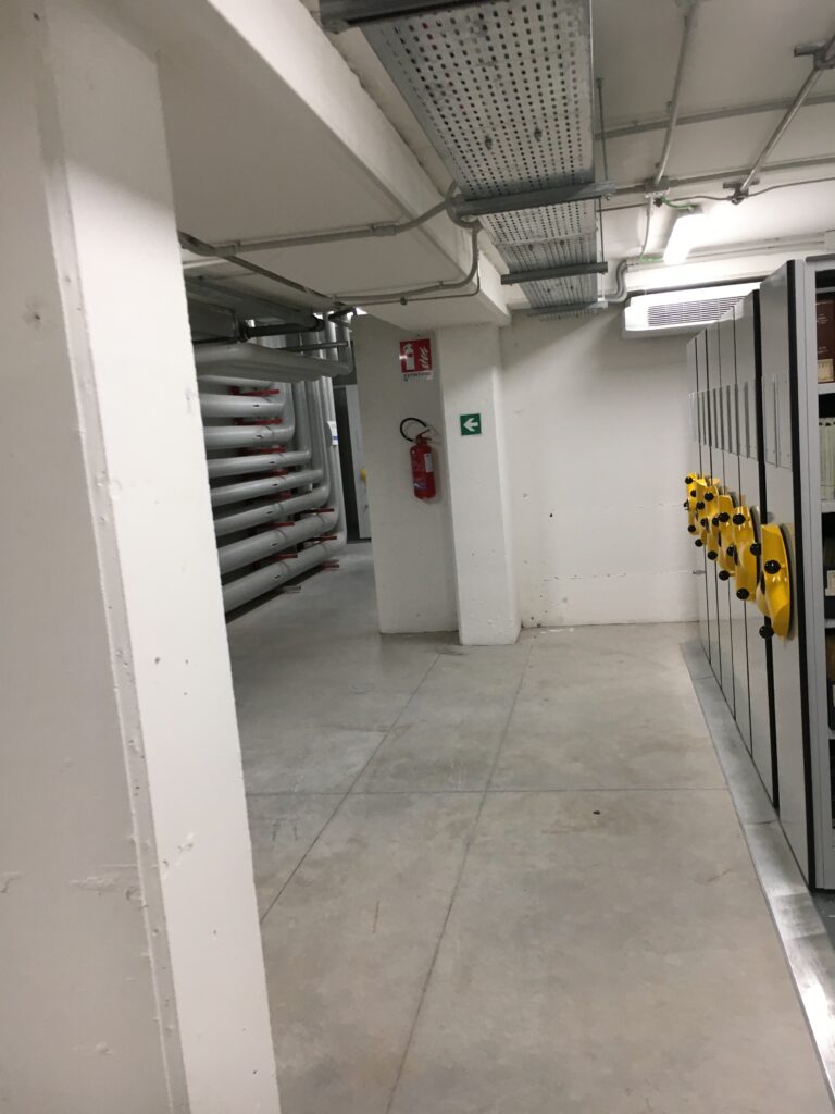
I usually call the first site visit “the photoshoot”: while the contact person guides me around the premises, I ask questions and take pictures. Later I will return, taking measures, usually alone, but the photoshoot is focused on getting the most from my guide’s time.
I use the “stream of consciousness” photographic method: starting from the main entrance, I document the journey in the building every 3-4 m, at every turn, stair, door, floor sign or fire escape plan. I like to have pictures of the ceiling, cabling, MDF, outstanding furniture. Later at the office it will be easy to review the picture stream and compare it to my memory of the journey. Months after the visit, when you ask yourself “What was the ceiling like in room 1505?” this method allows me to find the right information among hundreds of pictures.
My contact person walked me around the library warehouse and kindly answered my questions. The whole warehouse is located underground and is quite big. It has just one landline phone, no cellphone coverage, some weak wifi signal leaking from the floor above. I helped my guide express her use cases in this way:
A a librarian, I need to use the laptop to access the database while I am doing work inside the compactus aisles.
As a supervisor, I need a simple communication channel for colleagues in case of need while in the warehouse.
This translates in basic connectivity for web access from laptops, and chat apps on mobile devices.
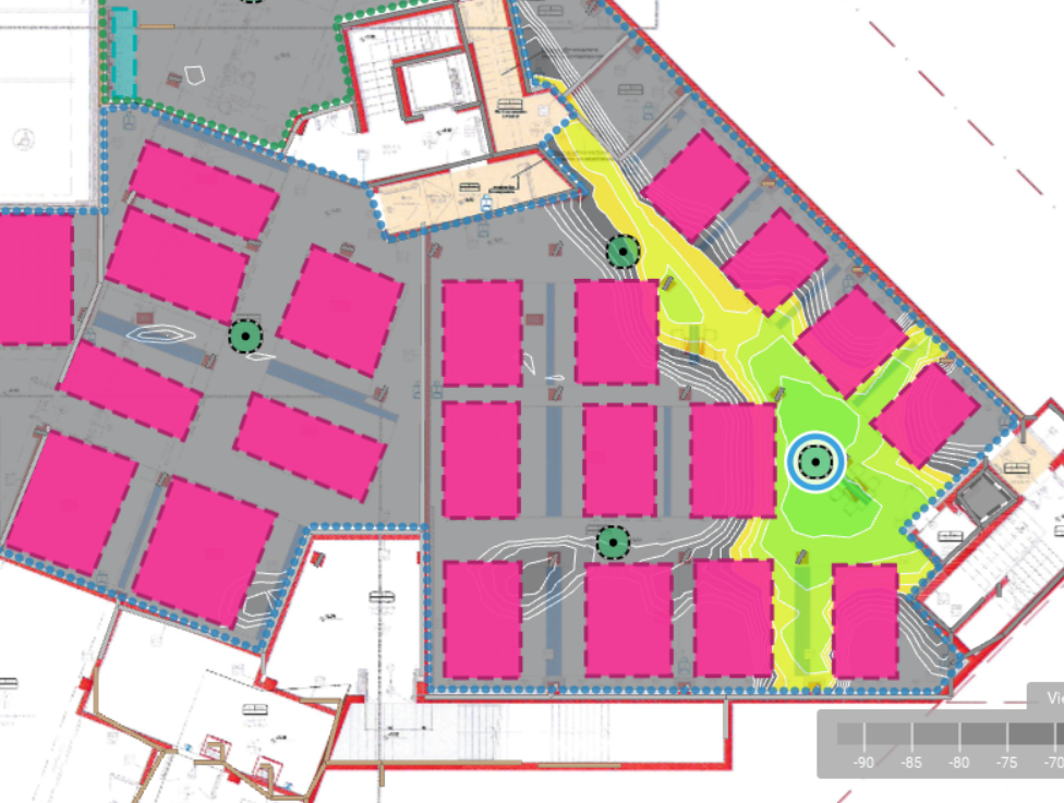
The next step at the office was to develop the predictive project, defining areas, requirements, walls and attenuation areas. I created a custom attenuation object for the compact racks, 2.5m high and 27dB/m. My reasoning is that the sturdy metal shelves and the material inside will totally block any wifi signal.
This project will focus on coverage for low density areas, with simple 2×2:2 ac Extreme Networks 3915 APs .
The predictive signal from an AP placed on the ceiling 1m above the compact shelving does not travel very far down the aisles. In the picture below a simulated AP is placed at 3.5m height, the shelves are 2.5m high. Please note that the default predictive signal in Ekahau is simulated at 1m above the floor.
Predictive signal strength on 5Ghz at 14 dBm (18dBm EIRP)
Predictive design in Ekahau simulates the signal attenuation caused by free space path loss and wall/obstacle attenuation. It does not factor in reflection and other complex RF propagation effects. But here the environment is very complex: on the ceiling there are metal conduits, cabling trays, concrete rafters, low-ceiling areas and shelves of different size and model.
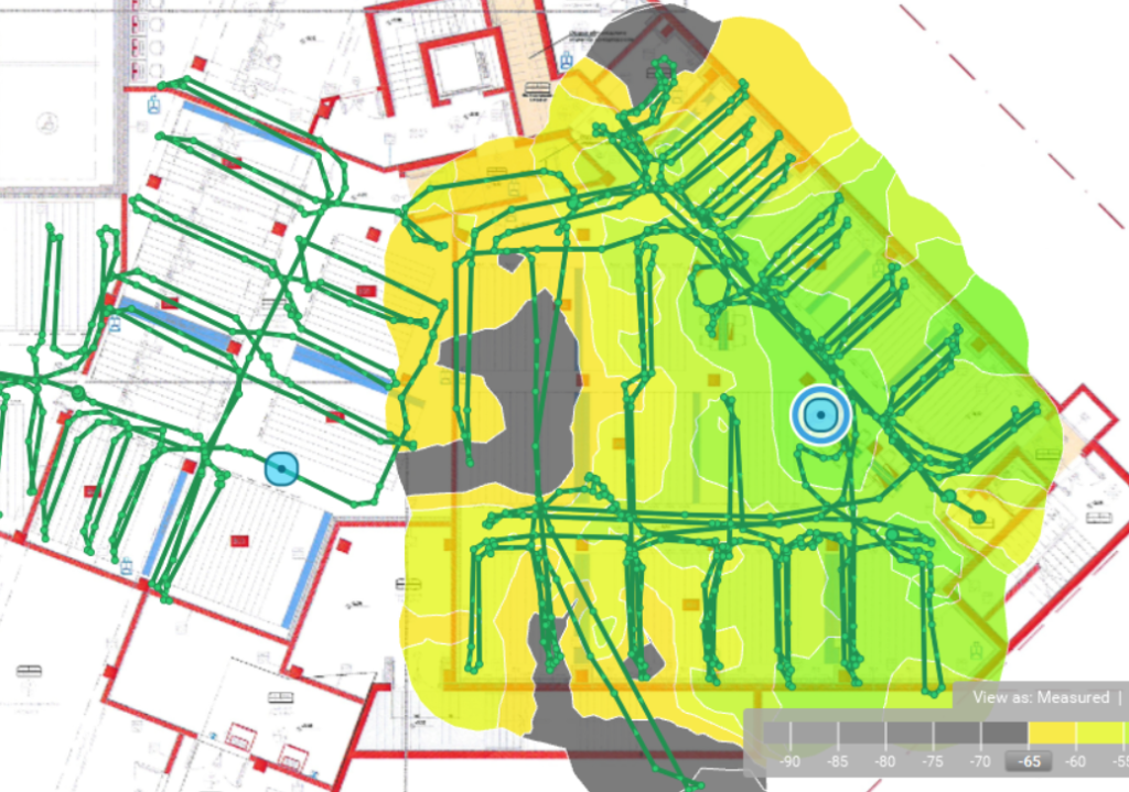
To validate the predictive design with actual measurements on site, let’s do an AP on a stick survey! I gathered my survey gear and headed to the library. After placing the APOS in a specific position I walked in a sliding aisle every 4 racks measuring the signal with the Sidekick. This time I was on my own, al the doors were open and the area was freely accessible and very quiet. I really enjoyed the time spent most productively there.
Placing an AP in the same position as the simulated AP above gave very encouraging results. The signal is pretty good inside the shelves, even far away from the AP.
5Ghz at 12 dBm (16 dBm EIRP), as measured
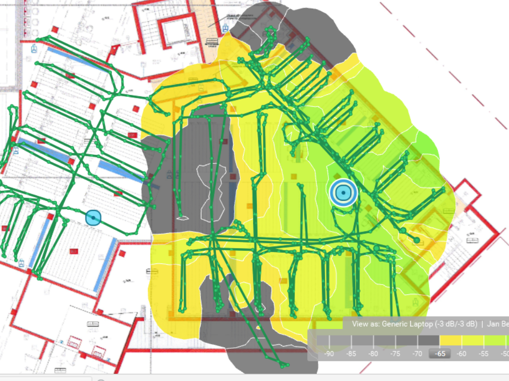
Adding a small offset to the measured data still shows decent coverage in awkward locations. The AP could be moved to a more central position, or the EIRP increased slightly.
5Ghz at 12 dBm (16 dBm EIRP), viewed as generic laptop -3dB
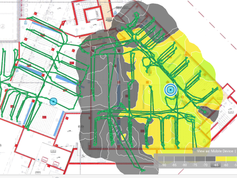
Even the notorious mobile device offset (around -10 dB) shows a workable coverage. Clients in the gray areas may choose 2.4 Ghz, the EIRP could be increased, or there would be just low RSSI and basic data rates.
5Ghz at 12 dBm (16 dBm EIRP), viewed as mobile device -10dB
The difference in the results from predictive design and from APOS can be explained perhaps as an excessive attenuation value in the predictive model. My personal view however is that multipath has an important role in that complex environment.
Based on the results on the field, I designed the whole library warehouse using a reasonable number of APs. The project is underway and I will share the validation results once it’s installed.